Industrial Gearbox systems appear in equipment that must move heavy loads steadily, from conveyor belts and mixers to pumps and cranes. They transfer power from a motor to a machine while changing speed and torque. Inside the housing, meshing gears guide motion through supported shafts and bearings. The result may be slower rotation with greater turning force, or another speed suited to the task.
This guide explains what an Industrial Gearbox is and how its main parts work together. It also introduces common gearbox types, gear ratios, lubrication, and practical selection factors. A technician might inspect the oil level, listen for a new whine, or check housing temperature during routine maintenance. These observations can reveal developing wear, though they do not replace measurements or the manufacturer’s service instructions. Details matter.
Gearboxes are not interchangeable boxes of gears. A unit designed for a slow, high-load conveyor may not suit a fast packaging line, even if their power ratings appear similar. Selection depends on load, speed, operating hours, environment, mounting position, and required service life. In real installations, alignment and lubrication can matter as much as the catalogue rating. That is easy to overlook. This overview offers a practical foundation. One question remains: does the gearbox suit the machine’s actual duty, not just its nameplate?
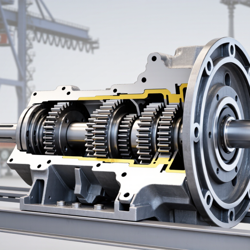
What an Industrial Gearbox Is and What It Does
An industrial gearbox is a mechanical assembly that changes how power moves from a motor to a machine. It usually contains meshing gears inside a rigid housing, with shafts, bearings, and lubricant supporting smooth operation. You may find one driving a conveyor, mixer, pump, or lifting system. The exact layout depends on the load and available space.
A gearbox can reduce speed while increasing output torque, or raise speed when the application calls for it. It does not create power; friction and heat mean some input energy is lost. For example, a conveyor may need steady, controlled movement rather than a motor’s faster rotation. Gear ratio, load, duty cycle, mounting position, and lubrication all affect the choice. A calculation can look sound on paper yet miss frequent starts or shock loads. That happens. Check the actual operating conditions, not just the motor rating.
Tips: Match the gearbox to the machine’s real workload. Confirm shaft alignment and mounting before startup. Use the lubricant grade and inspection intervals specified for the unit. Listen for new noise, and watch for leaks or unusual heat. Small changes matter. A temperature reading alone cannot diagnose a fault, so compare it with the unit’s normal operating pattern and consult qualified maintenance personnel when readings change.
Key Components Inside an Industrial Gearbox
What Is an Industrial Gearbox and How Does It Work?
Key Components Inside an Industrial Gearbox
An industrial gearbox transfers power from a motor to driven equipment. Its housing holds the working parts and helps keep contaminants away. Inside, the input shaft carries power to meshing gears. Their tooth sizes and arrangement change rotational speed and torque. A lower output speed often means greater torque, though actual performance depends on the gearbox design and operating conditions.
Gears need support and lubrication. Bearings keep shafts aligned while allowing them to rotate with less friction. Oil or grease forms a protective film between moving surfaces and helps carry away heat. Seals limit lubricant leaks and block dust or moisture. Small details matter. A worn seal may seem minor, but contamination can damage gears and bearings. A clean-looking housing can still hide internal wear, so appearance alone is not a reliable condition check.
Tips: Check lubricant level and leaks during routine inspections. Listen for new knocking or whining sounds, and note unusual heat near the housing. Follow the equipment maker’s service guidance; lubricant needs vary with gearbox type, load, and temperature. Some checks are easy to overlook.
How Gears Transfer Power and Change Motion
An industrial gearbox changes the relationship between speed and torque. Inside its housing, meshing teeth pass rotation from one shaft to another. A small driving gear turning a larger gear slows the output and increases torque. Reverse that arrangement, and output speed rises while available torque falls. The gear ratio sets this trade-off.
On a conveyor, for example, a motor may spin too quickly to move a loaded belt steadily. A gearbox reduces shaft speed, helping the drive pull the load without demanding the same speed at the belt. Gear shape matters, too. Spur gears are simple; helical teeth engage more gradually, often making operation quieter. But tooth contact still creates friction and heat. A ratio alone tells little.
The International Energy Agency’s 2011 report, Energy-Efficiency Policy Opportunities for Electric Motor-Driven Systems, estimates that these systems use about 46% of global electricity. The U.S. Department of Energy’s 2014 Improving Motor and Drive System Performance sourcebook puts motor-driven systems at roughly 70% of U.S. manufacturing electricity use. These figures describe complete systems, not gearboxes alone. That distinction matters. In practice, alignment, lubrication, load, and operating hours affect performance; even a well-chosen gearbox can waste energy when poorly maintained. One detail is easy to overlook: the smoothest-running unit is not automatically the right one.
What Is an Industrial Gearbox and How Does It Work? - How Gears Transfer Power and Change Motion
| Gearbox Type |
How It Transfers Motion |
Typical Reduction Ratio |
Typical Efficiency |
Common Industrial Uses |
| Helical |
Angled teeth engage gradually, transmitting power smoothly between parallel or crossed shafts. |
About 1.5:1–6:1 per stage |
Approximately 95–99% per stage |
Conveyors, mixers, pumps, and general-purpose machinery |
| Spur |
Straight teeth mesh between parallel shafts; the simple arrangement changes rotational speed and torque. |
About 1.5:1–6:1 per stage |
Approximately 95–99% per stage |
Packaging equipment, material handling, and low-to-moderate-speed drives |
| Bevel |
Conical gears transfer rotation between intersecting shafts, commonly changing the drive direction by 90°. |
Often about 1:1–5:1 per stage |
Approximately 95–98% per stage |
Right-angle drives, crushers, and machinery with intersecting shaft layouts |
| Worm |
A screw-like worm drives a meshing wheel, providing high reduction in a compact, right-angle arrangement. |
About 5:1–100:1 in one stage |
Approximately 50–90%, depending strongly on ratio, design, and operating conditions |
Lifts, conveyors, positioning equipment, and compact right-angle drives |
| Planetary |
A central sun gear drives planet gears that rotate inside a ring gear, sharing the load across multiple meshes. |
About 3:1–10:1 per stage |
Approximately 95–98% per stage |
Robotics, heavy-duty drives, mobile machinery, and applications requiring high torque density |
| Multi-stage gearbox |
Two or more gear stages combine their reductions to produce a larger overall speed reduction. |
Overall ratio is the product of the individual stage ratios |
Overall efficiency is lower than the efficiency of a single stage |
Heavy industrial drives, mills, large conveyors, and low-speed equipment |
How the numbers relate: A reduction gearbox lowers output speed and increases available output torque. For example, with a 10:1 reduction and 96% gearbox efficiency, an input speed of 1,500 rpm produces approximately 150 rpm output speed. The ideal torque multiplication is 10 times; after accounting for efficiency, output torque is approximately 9.6 times input torque. Actual ratios and efficiency depend on the gearbox design, lubrication, load, and operating conditions.
Common Types of Industrial Gearboxes
Industrial gearboxes change a motor’s speed and torque to suit a machine’s workload. Inside, meshing gears transfer rotation through a sealed housing, while bearings support the shafts. Spur gearboxes use straight teeth and work well for simple, parallel-shaft drives. They are efficient and straightforward to maintain, though tooth contact can create noticeable noise at higher speeds. Helical gearboxes use angled teeth that engage gradually. They often run more smoothly under load, but can create axial thrust that the bearings must handle. Simple, but not silent.
Bevel gearboxes transfer motion between shafts that meet at an angle, often 90 degrees. They fit compact layouts such as right-angle conveyors or mixers. Worm gearboxes use a screw-like worm and a toothed wheel, usually with perpendicular shafts. They can provide substantial speed reduction in a small space, but sliding contact may generate heat and reduce efficiency. Not always the best choice for continuous, high-load operation.
Planetary gearboxes place several planet gears around a central sun gear, with an outer ring enclosing the assembly. Their compact design can deliver high torque and distribute loads across multiple teeth. Selection depends on more than the gearbox type: check required speed, peak torque, duty cycle, mounting position, and operating temperature. A unit that looks adequate on paper may overheat in a dusty enclosure or during frequent starts. Allowing for real operating conditions is easy to overlook.
Where Industrial Gearboxes Are Used and How They Are Selected
Industrial gearboxes are used wherever equipment needs controlled speed and higher output torque. Typical settings include conveyor lines, mixers, crushers, hoists, and water-treatment equipment. On a conveyor, a gearbox reduces a fast motor’s speed so loaded belts move steadily rather than jerk. In a mixer, the required torque may change as material thickens. Conditions matter.
The U.S. Department of Energy’s 2014 report, Improving Motor and Drive System Performance: A Sourcebook for Industry, estimates that motor-driven systems use about 68% of U.S. industrial electricity. That makes efficient matching important, though the gearbox alone does not determine total energy use. Selection starts with the driven machine’s required speed and torque, then considers operating hours, starts per hour, shock loads, and ambient temperature. A dusty, hot plant may need different sealing and lubrication than a clean indoor line. Small details count.
A common mistake is choosing by motor power alone. Check the gearbox’s service factor, thermal capacity, mounting position, and allowable output loads against real operating conditions. Leave room for maintenance access. A neat catalog match can still be wrong if the load surges at startup or runs continuously. Even good calculations need field verification.
Conclusion
An Industrial Gearbox is a mechanical unit that manages how power moves from a motor to a machine. By changing rotational speed and torque, it helps equipment operate at a rate and force suited to its task. Inside, gears are supported by shafts, bearings, a housing, and lubrication. These components work together to carry loads, reduce friction, and keep motion controlled.
As gears of different sizes or arrangements engage, they can slow rotation, increase torque, or redirect motion. Common designs include helical, bevel, planetary, and worm gearboxes, each suited to different space, load, and operating needs. Industrial gearboxes are used in equipment such as conveyors, mixers, cranes, and production machinery. Choosing one involves considering the motor’s power and speed, required output torque, load conditions, operating environment, available space, and maintenance requirements. A well-matched gearbox can support reliable, efficient operation over time.

 Kineto Motor